The blue dot and the WGS84 coordinates after having performed the geo-referencing process
What is a geo-referencing process?
After having performed a proper mapping of the environment you can perform the geo-referencing process. The geo-referencing process is a one time process that allows Dragonfly to determine the link between the features inside the 3D map and the real world distances and it is done by telling to Dragonfly what are the features seen when the camera is placed at some reference points (called markers) using either:
- a high quality floor plan of the area of interest – GOOD accuracy + dot location shown on the floor plan.
- or a DWG file of the area of interest – HIGHEST accuracy.
At the end of the geo-referencing process, Dragonfly will be ready to be used in production and it will provide the positions as:
- WGS84 coordinates – latitude and longitude.
- metric coordinates – relative distances in meters from:
- the center of the north aligned version of your floorplan (if available).
- or from any origin specified with this API.
- altitude – from the ground (in meters).
 Important info about “accuracy/validity of the coordinates returned” VS “geo-referencing process chosen”
Please read this article with more information about the meaningfulness of the metric and WGS84 coordinates returned by the Dragonfly App when a specific geo-referencing method is chosen.
How to perform a geo-referencing process
Step 1 – Choose the equipment for the geo-referencing
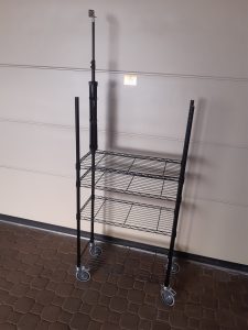
Because of the fact that the moving asset might be cumbersome, it might become difficult to ensure that the camera (mounted on the moving asset) is accurately positioned over the spots chosen for geo-referencing process! This is why we suggest to do the geo-referencing process with the camera attached firmly to an extendable stick that is attached in turn to a trolley with wheels (on which you can carry around a laptop with the Dragonfly App running. Doing so:
- the extendable stick will allow you to set the camera at the same altitude at which the camera will be used in production.
- the small size of the trolley will allow you to accurately position the trolley (and thus the camera) over the reference points chosen for the geo-referencing process!

Step 2 – Plan the number and the locations of the markers
To plan for the markers, the IMPORTANT information to be kept in mind are these:
- The minimum number of markers is 3. After the placement of the 3rd marker, Dragonfly will start providing the WGS84 coordinates of the camera. Nonetheless, you can place also additional markers if the area to be mapped is more complex than a simple square or rectangular.
- Regardless of the total number of markers set for your venue, in order to compute the position, Dragonfly uses the 3 markers closest to the estimated position of the camera in real-time.
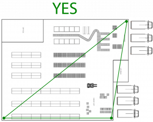
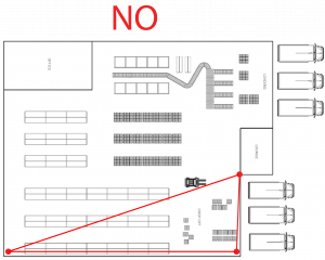
- Dragonfly provides the highest accuracy within the virtual polygon created by connecting the 3 markers closest to the estimated position of the camera. So, if your position falls outside any of the virtual polygons created by connecting 3 markers closest to the estimated position, then that position might be less accurate.
Good and bad choices for placement of the 3 markers
Step 3 – Set the markers
The markers can be provided to Dragonfly at runtime in 2 different ways:
- OPTION 1 – pin-pointing the location of the camera on a floor plan when the camera is physically in different locations. If you would like to pursue this option, then the very first thing you need to do NOW is to upload a detailed and well-scaled floor plan of the area inside the Dragonfly Cloud Dashboard following these steps.
- OPTION 1.2 – or by entering the metric coordinates of each virtual marker taken from a DWG of the venue inside the Dragonfly Web User Interface (this is what we suggest to get the MAXIMUM accuracy!).
OPTION 1 – Set VIRTUAL markers
The process to define virtual markers is the following:
- Start Dragonfly and select the Configuration tab.
- Inside the Calibration method field select Three markers used (either printed or virtual)”.
- Click on Save Config and Restart.
- Click on the Maps tab and Load the map previously created. If you don’t have a map then it means that you have skipped this page!
- Select the View tab.
- DO NOT activate the NAVIGATION ONLY checkbox!
- Press on the GREEN PLAY button to start the positioning. The video preview should be displayed.
- If you get an error message about the video stream not available please check the pages “Configure Dragonfly > Connect the camera” available in the left sidebar.
- If you get the error “NOT authenticated” please check this page.
- Move your camera to start detecting the features associated to the shapes and objects in your environment.
- By now the Status shown to the right of the GREEN PLAY button will switch from MAP INIT to MAPPING. During the process described in the next lines, if the status shown to the right of the GREEN PLAY button switches from MAPPING to LOST you have to move back to the area already mapped until the status switches back to MAPPING and then you can keep following the process outlined.
- Move with the camera towards the first remarkable location where you will collect the first virtual marker. A remarkable location is a location inside your venue that can be identified without doubts inside the floor plan image and/or inside the DWG file of the venue. When the location is reached:
- OPTION 1
- press the Map calibration button and select the level that contains the floor plan previously uploaded.
- pin-point on the floor plan the current location of the camera. A pop-up asks for the altitude value. Enter the current real altitude of the camera (measured with a laser, for example).
- click Save marker.
- OPTION 2
- open the DWG file with the metric coordinates of your venue (you can use DWG TrueView).
- retrieve the metric coordinates of the current location of the camera.
- click on the Metric markers button and enter the metric coordinates and the current real altitude of the camera (measured with a laser, for example). Leave the Reference longitude field to 0.
- OPTION 1
- Move with the camera towards the second remarkable location where you will collect the second virtual marker. A remarkable location is a location inside your venue that can be identified without doubts inside the floor plan image and/or inside the DWG file of the venue. When the location is reached:
- OPTION 1
- pin-point on the floor plan the current location of the camera. A pop-up asks for the altitude value. Enter the current real altitude of the camera (measured with a laser for example).
- click Save marker.
- OPTION 2
- open the DWG file with the metric coordinates of your venue (you can use DWG TrueView).
- retrieve the metric coordinates of the current location of the camera.
- click on the Metric markers button and enter the metric coordinates and the current real altitude of the camera (measured with a laser for example). Leave the Reference longitude field to 0.
- OPTION 1
- Move with the camera towards the third remarkable location where you will collect the third virtual marker. A remarkable location is a location inside your venue that can be identified without doubts inside the floor plan image and/or inside the DWG file of the venue. When the location is reached:
- OPTION 1
- pin-point on the floor plan the current location of the camera. A pop-up asks for the altitude value. Enter the current real altitude of the camera (measured with a laser for example).
- click Save marker.
- OPTION 2
- open the DWG file with the metric coordinates of your venue (you can use DWG TrueView).
- retrieve the metric coordinates of the current location of the camera.
- click on the Metric markers button and enter the metric coordinates and the current real altitude of the camera (measured with a laser for example). Leave the Reference longitude field to 0.
- OPTION 1
- If needed, you can collect additional virtual markers following the steps above. But please keep in mind the information contained inside Step 2 and do not exaggerate with the number of virtual markers collected!
- If you have performed the geo-referencing process using the floor plan image you can now click on the Position button to see your accurate position as a BLUE dot on the floor plan!
- You can now create a new map that includes the virtual markers collected. To do so, click on the Maps tab and New Map button, assign a NAME and a DESCRIPTION to the new map and click on SAVE.
- Move with the camera towards the first remarkable location where you will collect the first virtual marker. A remarkable location is a location inside your venue that can be identified without doubts inside the floor plan image and/or inside the DWG file of the venue. When the location is reached:
Colored dots are visible inside the video preview. The colors (and sizes) of the dots correspond to the distance of the features to the camera: big blue dots are associated to the features detected on close objects, while small red dots are associated to the features detected on objects far away.
Information shown inside the Dragonfly Web User Interface
On the left side of the screen there are these info:
- Map – name of the current map (if already saved).
- FPS – it provides an indication about the speed at which the system runs (it must be higher than 20 FPS to produce good results).
- Markers – number of detected virtual markers.
- Map Points – number of features associated to objects/shapes detected in your environment and part of the current map.
- Level ID – the ID of the current level.
- Floor plans – number of floor plans.
At the bottom right side of the screen there are these info:
- Latitude, longitude and altitude (in meters)
- Pitch, Yaw and roll – orientation of the device (more info inside this page).
- X [m], Y [m] – distance in meters from the center of the floor plan (if no other origin is specified with this API).
- X is positive when moving to the right. Negative when moving to the left.
- Y is positive when moving to the top. Negative when moving to the bottom.
Please send us the information listed inside this page.

